Plumbing: Flow Rates, Design & Balancing

Plumbing the Rock Trap
Plumb the supplied Rock Trap (25577-950-000) just before the water line reaches the waterfall inlet.

Flow Performance Guidelines
The water feed line from the pump to the waterfall should use a minimum of 1½” PVC pipe. The feed line should terminate near the center of the waterfall at the back of the bond beam. Use a minimum of 2″ pipe for runs over 60′.
Maximum Recommended Flow Rates:
– Use 1½” Pipe for 60 GPM
– Use 2″ Pipe for 100 GPM
– Use 2½” Pipe for 140 GPM
– Use 3″ Pipe for 225 GPM
Plumbing Design
– Use a minimum of 1½” PVC pipe for all waterfalls.
– Use a minimum of 2″ pipe for runs longer than 60’ in length or for waterfalls over 60″ long.
– Dedicated waterfall plumbing lines are recommended for best results.
NOTE: When plumbed correctly, Natural Wonders® Waterfalls are designed to minimize the amount of water that remains in the unit when not in use. Design the plumbing system to allow water to drain easily out and prevent damage from freezing.
Suctions & Filter Strainer
VGB compliant suction covers must be used for each suction line and they must be installed 18” above the bottom of the pool.
– Install at least two suctions per pump as required by law.
– A filter strainer is required between the pump and the waterfall.
– Installations requiring more than 60 gallons per minute may require two or more filters to be plumbed in parallel.
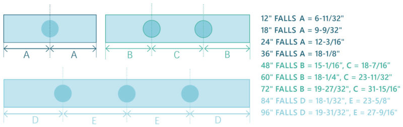
Inlet Spacing Guide
Waterfalls up to 36″ have one inlet.
Waterfalls from 48″ – 72″ have two inlets.
Waterfalls 84″ – 96″ have three inlets.

Balancing the Flow
– Use multiple pumps when installing multiple waterfalls. A separate line with a 3-way valve must be used to balance the water between the waterfalls.
– Use a 3-way valve as a “tee” from the return line of the pool to the waterfall for flow regulation. Locate the valve after the pump to allow the flow to be regulated between the waterfall and the pool return.
– The location placement for this valve is after the filter, near the equipment pad.

Multiple Waterfalls
When installing multiple waterfalls a separate pump is recommended.
– This will also require a separate suction line to be plumbed.
– Plumb the dedicated pump and suction with a minimum of 2″ PVC pipe.
NOTE: Installations requiring more than 60 gallons per minute may require two or more filters plumbed in parallel. Use a separate line with a 3-way valve to balance water between each waterfall.
Dry Wall Effect
Low flow installations may cause the mounting surface to become wet when the waterfall is flowing.
– To achieve a dry wall effect, it is best to aim for the higher end of the recommended GPM range.
NOTE: At the low end of the recommended GPM range the waterfall flume will still appear good, but you may be in the potential “drip zone.”
Example: For a dry wall on a 36″ waterfall, 36 GPM will give the best results.
Final Steps
Once pool construction is complete and the pool is filled with water, you may remove the protective tongue.
Be sure to check the spillway for debris and activate the waterfall.
If the waterfall is plumbed with the main filter pump, turn on the pump and run for five minutes to clear the lines of air and debris.
Then, open the regulating valve to slowly adjust the flow of the water until the sheeted water reaches the desired location on the pool surface.
![]()
Congratulations!
You have completed this chapter. To go to the next chapter, click next. To go back to the Chapter Table of Contents, click done.