Plumbing

PLUMBING LOCATION
All system components are inside the enclosure. Only the water inlet and outlet need to be installed into the pool return line.
Install the unit in the pool main return line after all other pool equipment (pump, filter, heater, and cleaner).
– The outlet must be at least 10 feet from the first return to the pool.
– Use the union fittings provided to connect the DEL AOP inlet and outlet to pool plumbing as shown above.
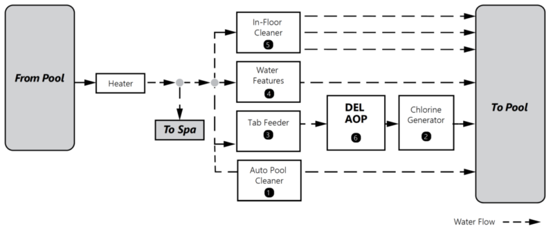
SYSTEM DIAGRAM
NOTE: DEL AOP works under a vacuum. The injector draws the ozone/air-gas mixture from the ozone cells and mixes it into the water leaving behind some undissolved gas bubbles. Because this can affect certain pool system components, care must be taken when installing DEL AOP.
This diagram covers some common plumbing configurations. For other configurations and assistance, contact www.c-m-p.com/support.
-
Pool Cleaners: Always plumb the cleaner T-fitting before DEL AOP to prevent gas from affecting cleaner operation.
-
Chlorine Generator: Always plumb after DEL AOP to prevent the trapped accumulation of hydrogen gas, a safety hazard.
-
Chlorine Tab/Mineral Erosion Feeder: Always plumb DEL AOP after any erosion feeder to avoid gas accumulating in the feeder. If installing as a retrofit and a tab feeder cannot be relocated, an MDV unit is recommended between DEL AOP and the tab feeder.
-
Water Features: Avoid plumbing the DEL AOP into any leg with excessive back pressure such as those going to fountains, restrictive wall fittings, etc.
-
In-Floor Cleaning System: Avoid excess backpressure by installing DEL AOP on a different pool return leg from any In-Floor Cleaning system. This will also prevent gas intrusion and high oxidizer levels in the zone valve and cleaner heads.
Installing an MDV?
![]()
NOTE: If installing a mixing de-gas vessel (MDV), allow 10 feet from the outlet of the MDV to the first pool return.
Under normal operation, bubbles will appear in the return flow to the pool. To remove the bubbles from the flow, an accessory Mixing De-gas Vessel, or MDV, can be installed downstream of the DEL AOP.
The MDV is designed for use with the DEL AOP and is recommended on indoor, covered, or vinyl-lined pools. It should also be used if a tab feeder in installed after the AOP system. For more information, please visit www.c-m-p.com/support.
No

MDV Install Location
The MDV must be plumbed downstream of the DEL AOP.
To avoid discoloration, mount in an area out of direct sunlight.
The outlet of the MDV XL must be at least 10 feet from the first return to the pool.
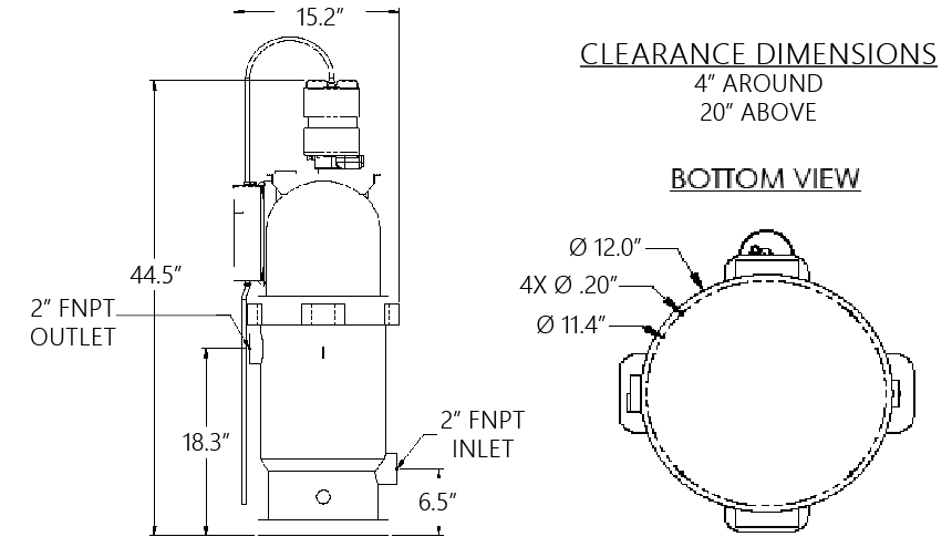
Verify Clearance
Verify footprint and clearance dimensions before placing the MDV XL on the equipment pad.
The MDV XL inlet and outlet fittings are 2” FNPT.
Use the correct fittings and thread sealant to plumb into the circulation loop.
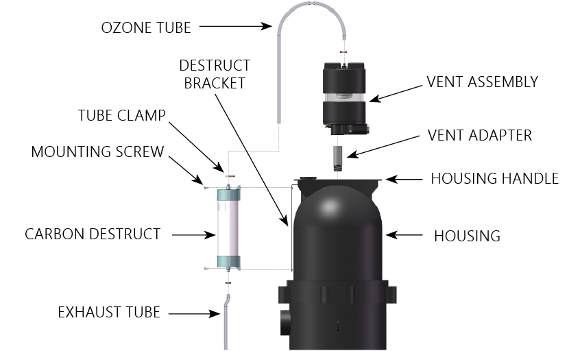
Assemble MDV Vent
Apply thread sealant to Vent Adapter threads.
Install Vent Adapter through the hole in the Housing Handle and into the Housing.
Use PVC primer and PVC glue to attach the Vent Assembly to the open pipe end of the Vent Adapter.
MDV Carbon Destruct
Mount the Carbon Destruct to the Destruct Bracket with the two Mounting Screws provided.
Connect the Ozone Tube and Exhaust Tube using the Tube Clamps.
– Tubing Clamps should be tightened behind the hose barb feature for proper attachment.
The Exhaust Tube will release small amounts of condensation and carbon under normal operation.
– To avoid water or carbon stains, route the Exhaust Tube to divert the condensation to a suitable location.
Confirm Final Installation
The MDV is optional and is not required to operate DEL AOP.
Under normal operation, bubbles will appear in the return flow to the pool.
Confirm AOP location and clearance before continuing.
CAUTION-WATER LEVEL
If the pool equipment is mounted above the water line, install a 2 inch CMP Hydroseal check valve (25830-400-000) between the pump outlet and the inlet of DEL AOP to prevent the pump from draining and losing prime when not in use.
Install Check Valve
If the pool equipment is mounted above the waterline, a check valve must be installed inline between the pump outlet and the AOP unit to prevent the pump from draining and losing its prime when not in use.
Is there elevated back pressure? [AOP 25 Only]
![]()
The AOP 25 will function best when the pool equipment is above water level and there are no accessories introducing additional pressure on the return line.
Are you installing an AOP 25 below water level or with possible elevated back pressure?
no
Flow Meter Test
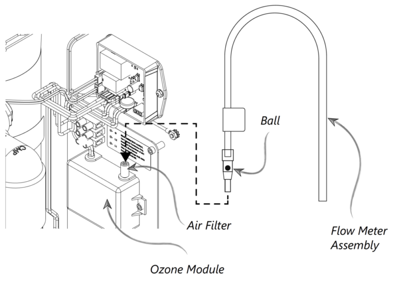
If there is any question of whether the injector is performing properly, a flow meter is provided in the parts kit to check for proper suction through the ozone cell.
– Operate the pool in the mode expected to introduce the highest return pressure.
– Remove the air filter from the ozone module.
– Attach the tubing from the flow meter to the ozone module.
– Hold the flow meter vertically and observe that the ball is above the “MIN” line. The ball may be bouncing but should average mostly above the line. The “MAX” marking can be ignored for this test.
– If the ball is not moving or is consistently below the “MIN” line, Install the orifice plate.
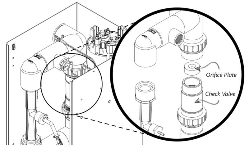
Installing the Orifice Plate
In cases where the return line pressure prevents proper operation, an orifice plate may be added to the inlet of the spring‐loaded check valve. This can improve injector performance.
– Loosen the union fittings on both the inlet and outlet of the check valve to remove it from the system.
– Insert the orifice plate on top of the check valve with the cone shape downward.
– Reinstall and tighten union fittings.
Leak Test
Turn on the pool circulation system and run at the highest normal operating pressure.
Check for leaks outside and inside of the AOP system. Correct any leaks outside of the system.
If any leaks are found inside the AOP, contact Customer Service at www.c-m-p.com/support.
Congratulations! You have completed this chapter. To go to the next chapter, click next. To go back to the Chapter Table of Contents, click done.
Do you need more help? You can find the best way to contact our team by clicking here.