Foundation: Preparation & Setting
Prep The Location
Once the area of installation is determined, mark off the area with stakes/ribbon/string prior to construction.
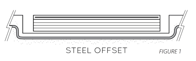
– When ready for rebar, mark the exact location of the waterfall.
– The steel pattern should be offset by 3″ to the bottom and by 1″ outside the length of the waterfall.
Example: If the waterfall is 24″ long, the steel pattern should offset to 3″ down from the top and 26″ in length.
Waterfall Body Installation
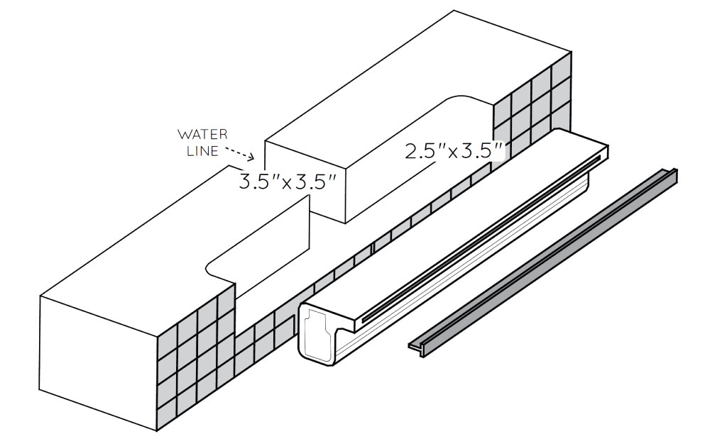
Cut the waterfall notch in the inner edge of the bond beam at the steel offset.
– The notch should be 3½” deep by 2½” wide and 2″ longer than the length of the waterfall ( 1” longer on each end ).
– Next, cut notches for 1½” plumbing behind the waterfall notch.
NOTE: Cover the finished setting with a piece of plywood ( 1/2” or 3/4” thick ) to assist in securing the waterfall until the concrete cures. Then, place heavy blocks evenly across the top of the plywood. This will also protect the waterfall from heat and sunlight which may cause warping.
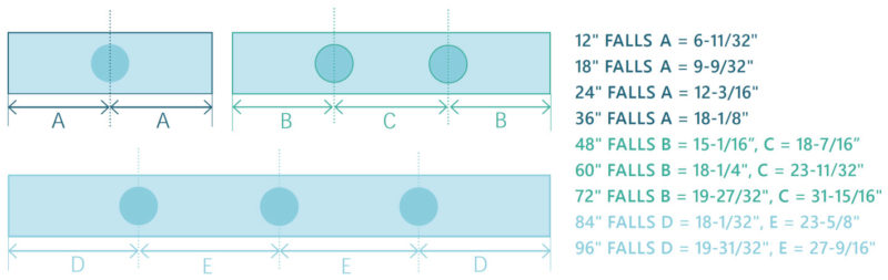
Multiple Ports
Waterfalls have one to three ports, depending on size.
– Refer to the waterfall diagram for notch and plumbing placement.
– Larger waterfalls will require multiple water lines.
– Each plumbing notch should be 3½” wide by 3½” deep.
Setting The Waterfall
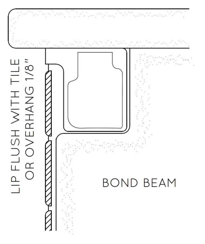
Place the waterfall in the notch cut in the bond beam.
– Using shims of tile, make sure the top of the waterfall is level with the upper edge of the bond beam.
– Fill the gaps around the unit and coat the face of the waterfall with concrete or similar material in preparation for the tiles.
– Then, cut the tile to fit under the lip of the waterfall using thin-set or a similar substance to secure in place.
NOTE: Always install the waterfall before the pool deck or coping.
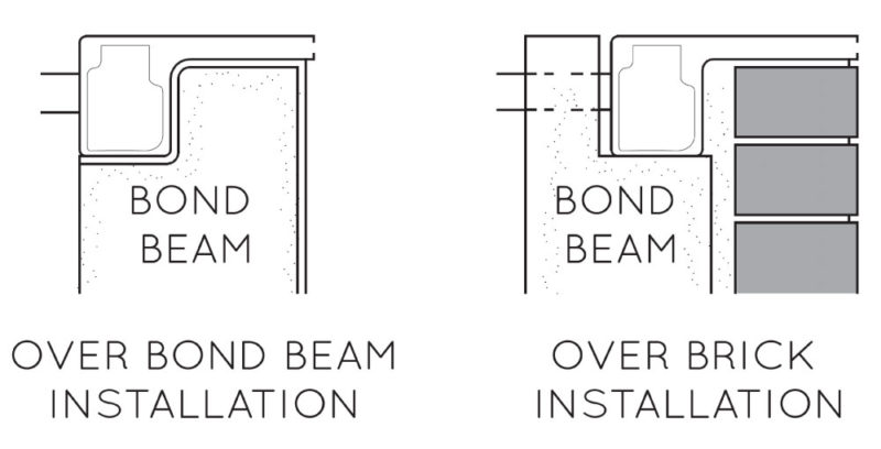
Extended Lip Applications
Some applications will require the use of an extended lip ( such as mounting in a radius or when using brick or blocks, etc ).
– The standard lip is 1″ while the extended version is 6″, 9″ or 12″.
– Installation of the extended version is identical to the previous steps.
– Because the entire span of the extended lip must be supported, the notch dimensions in the bond beam may need to be altered.
NOTE: Mortar will not adhere to the unit. Consult a decking or concrete professional to find the appropriate materials for installation.
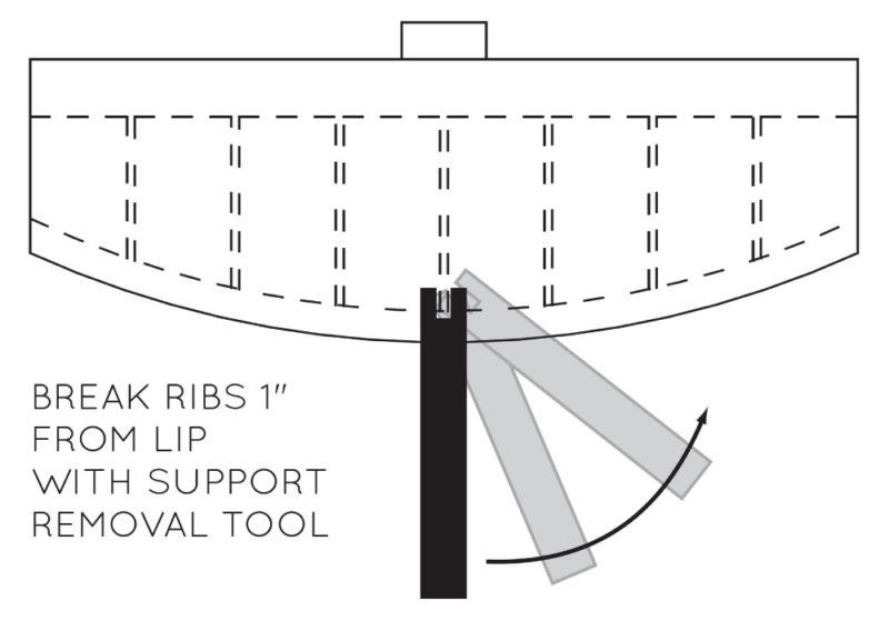
Cutting The Lip
Extended lip models can be cut to custom shapes in the field for different applications. Remove the protective insert before cutting the lip.
– Before beginning determine how much of the lip to remove. Allow room for the tile and thin-set, so that the lip will still be flush or protrude slightly beyond the tile line.
– Make sure you leave a minimum of 1½” of length in the lip after cutting.
– Use a coarse tooth blade, cutting carefully to avoid any jagged edges on the lip.
– Then, use the included rib removal tool to remove the ends of the exposed ribs at the edge of the cut. All ribs within 1″ of the opening should be removed.
NOTE: Do not leave the broken pieces in the unit. Sand the edge as smooth as possible using a sanding block. Then, replace the protective insert and continue with the standard installation.
![]()
Congratulations!
You have completed this chapter. To go to the next chapter, click next. To go back to the Chapter Table of Contents, click done.